 ar
ar bg
bg hr
hr cs
cs da
da nl
nl fi
fi fr
fr de
de el
el hi
hi it
it ko
ko no
no pl
pl pt
pt ro
ro ru
ru es
es sv
sv tl
tl iw
iw id
id lv
lv lt
lt sr
sr sk
sk sl
sl uk
uk vi
vi et
et hu
hu th
th tr
tr fa
fa ms
ms hy
hy ka
ka ur
ur bn
bn mn
mn ta
ta kk
kk uz
uz ku
ku
load cell wire diagram
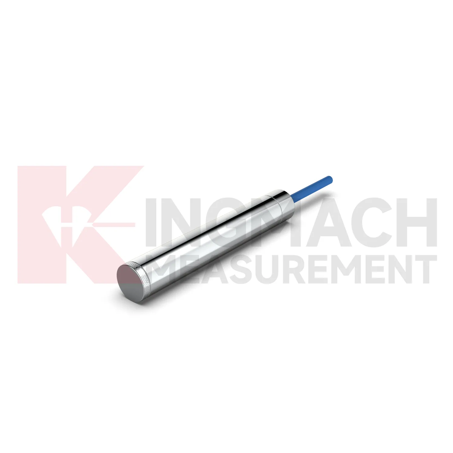
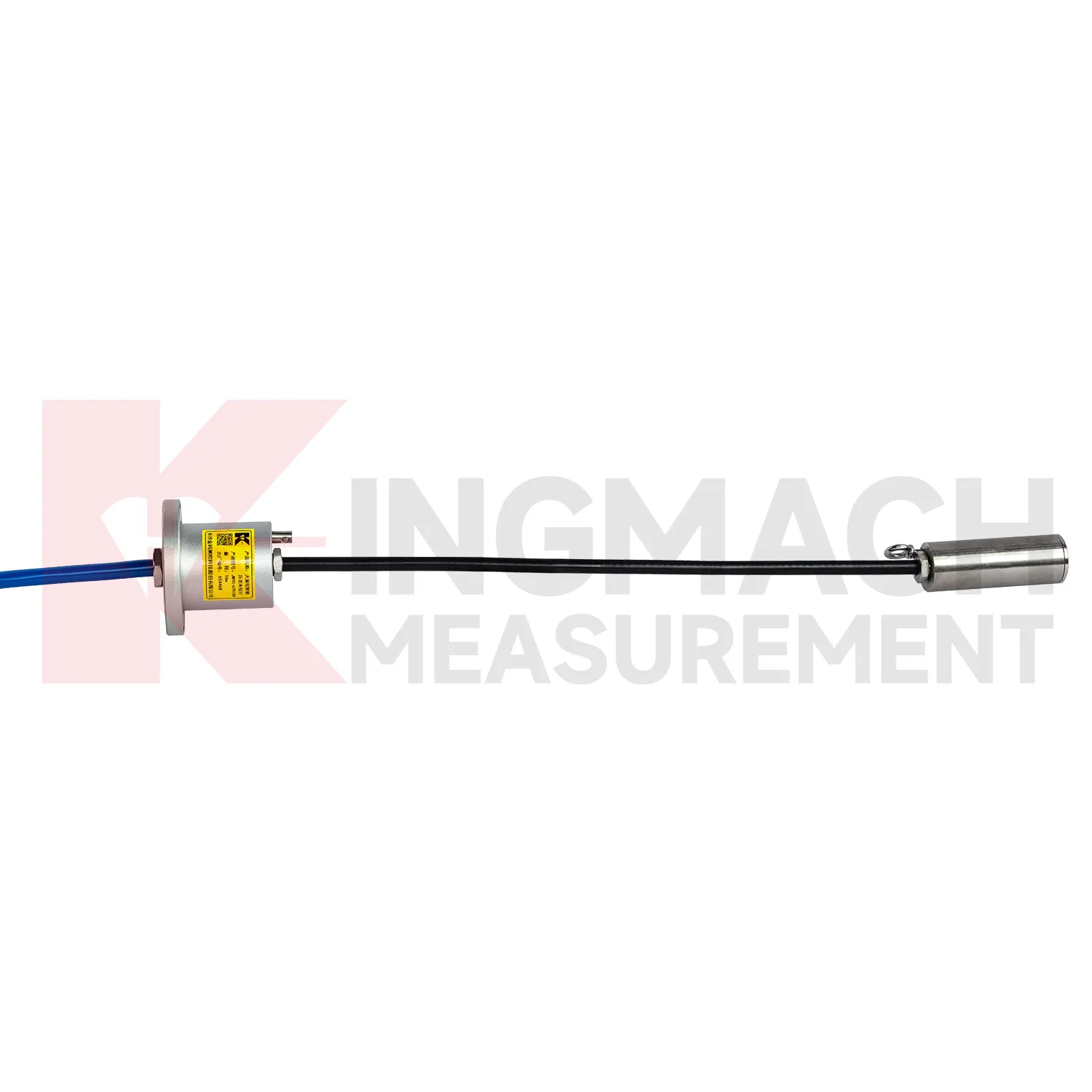
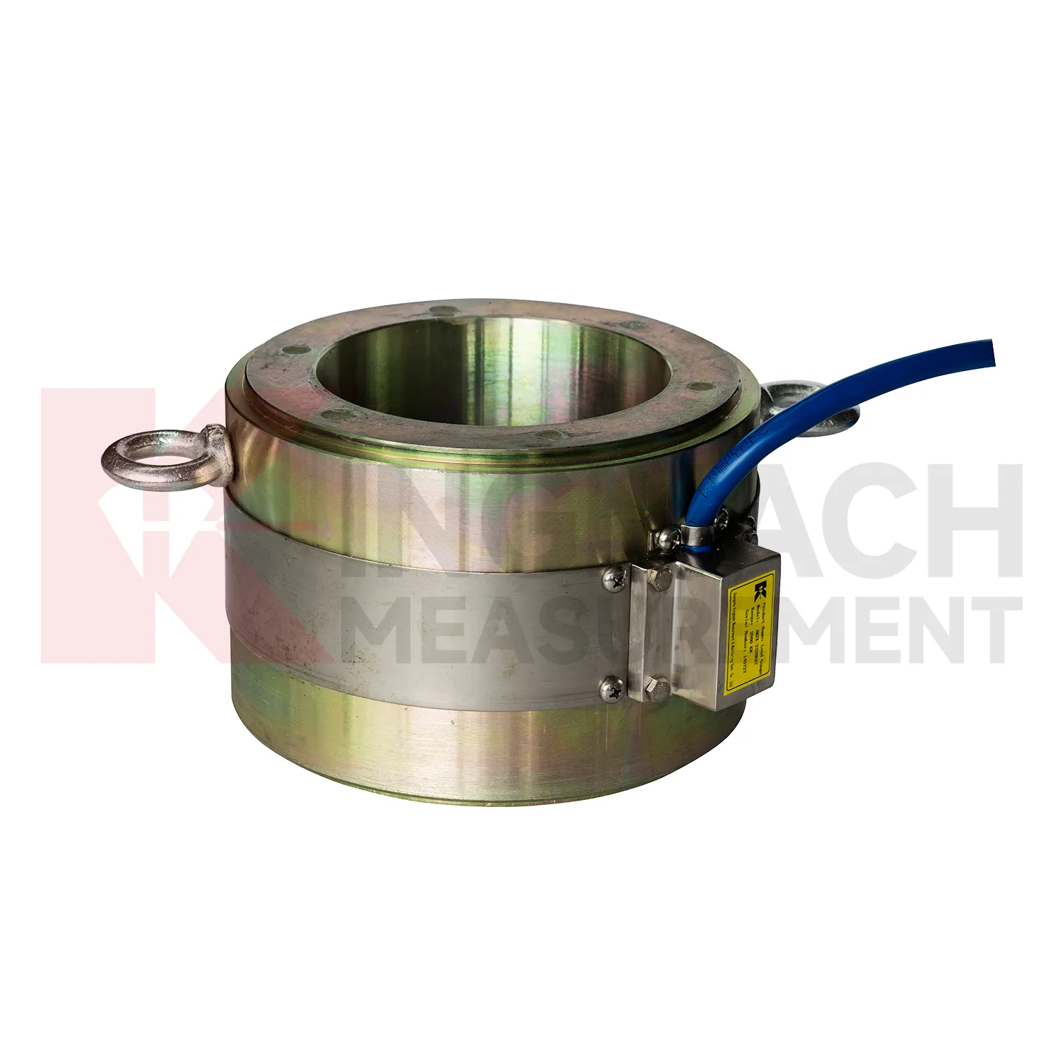
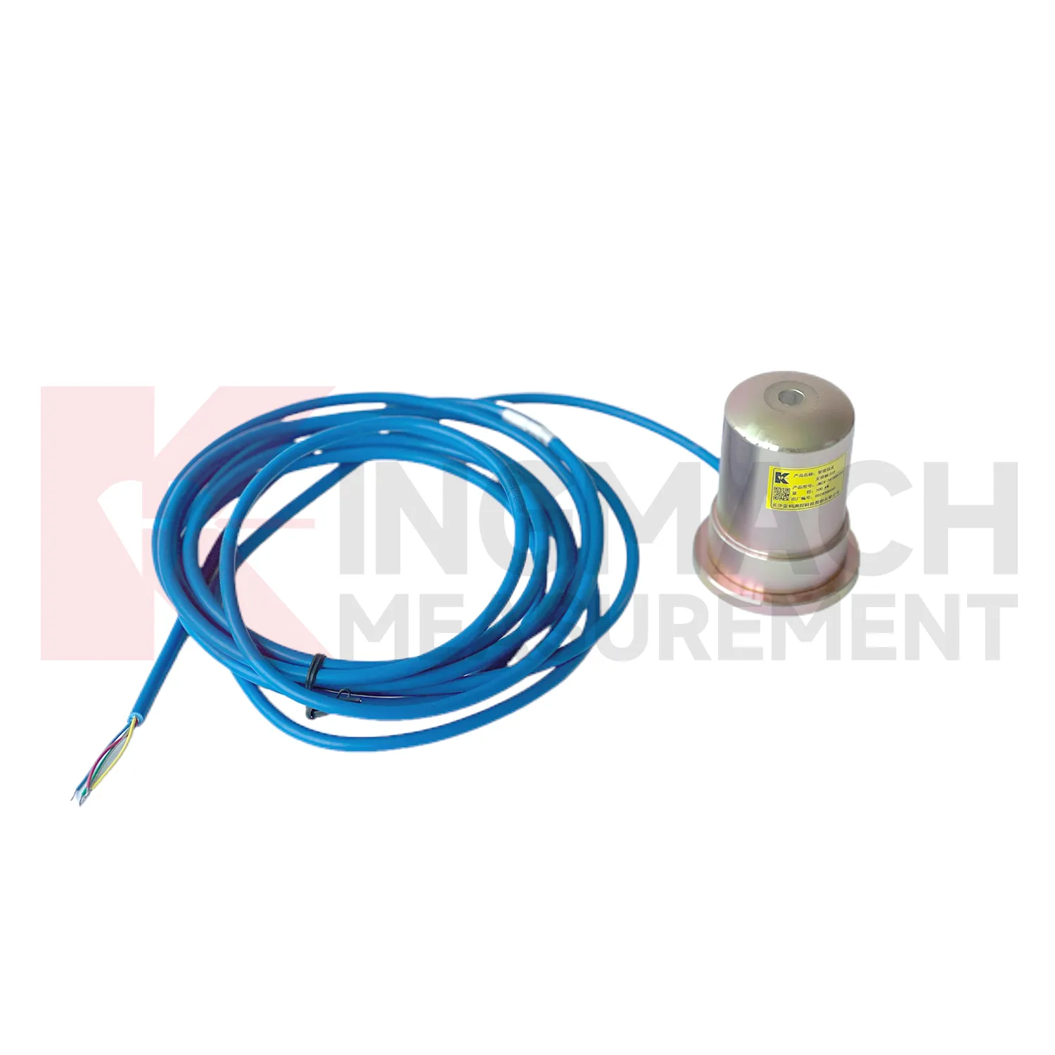
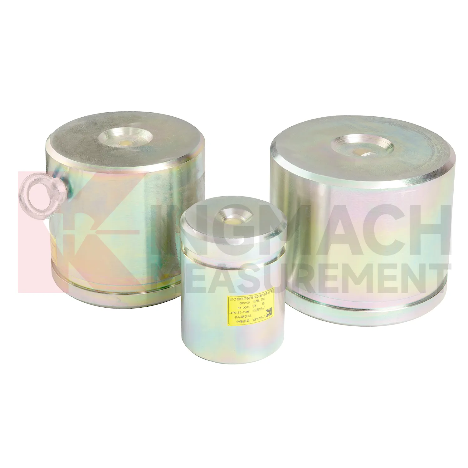
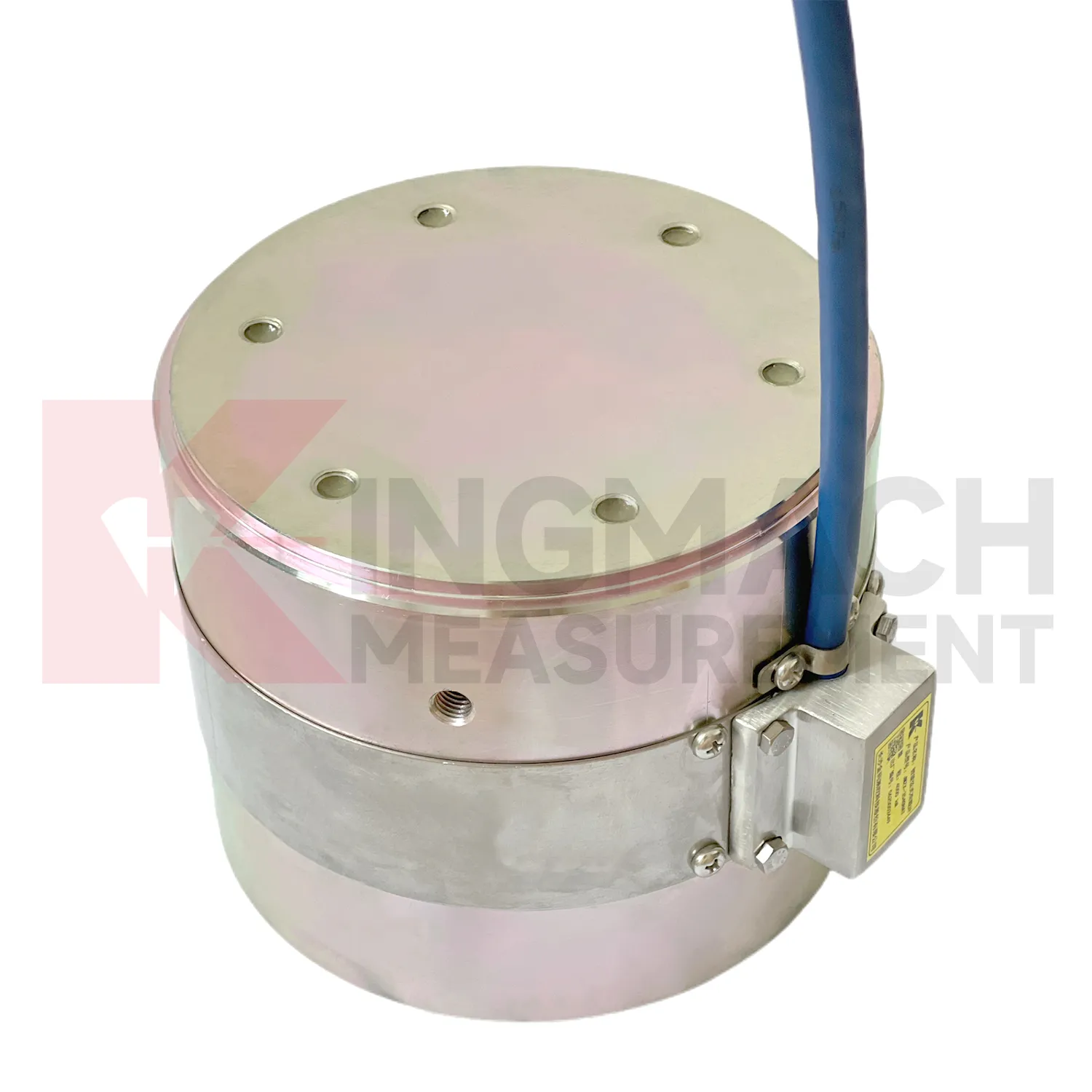
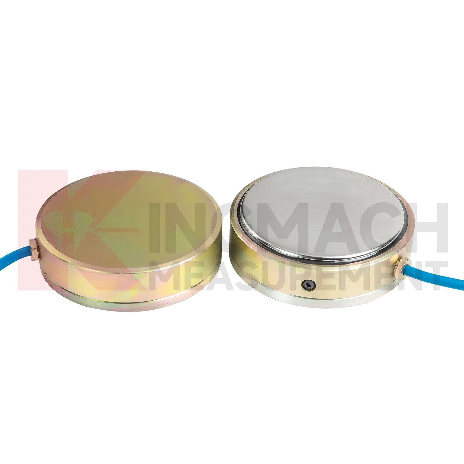
Kingmach load cell wire diagram product information is especially helpful during early engineering review because it gives model families rather than one generic device. The JMZX-3XXXHAT hollow load cell is tied to annular multi-string construction, elastic steel, ultra-high-strength vibrating wires, anchor welding, temperature correction, and 500 kN to 8000 kN ranges. The JMZX-35XXHAT solid load cell is tied to compression monitoring, 1000 kN to 10000 kN ranges, 0.1 kN resolution, and 0.5%FS precision. The JMZX-38XXHAT axial force meter is tied to steel support measurement, 200 kN to 3000 kN ranges, and 1 MPa waterproof performance. Those distinctions guide model selection before purchase. For a bridge, the force path may require hollow or solid construction. For a tunnel support, direct axial force display may be more practical. For soil pressure, MPa range and buried durability matter more than kN capacity. Matching the type to the load path prevents expensive changes after delivery. The product pages also show that standard models and customized versions may exist side by side. That is important because site geometry, force range, and available clearance may require confirmation before the load point can be ordered with confidence. It also gives the contractor clearer limits for installation geometry, cable routing, waterproof protection, and calibration review before the work reaches the field.
Application of load cell wire diagram
In pile load testing and bearing capacity verification, load cell wire diagram helps track applied force, load stages, unloading response, and residual behavior. The common problem is uncertainty around whether the applied load is centered and whether the recorded value matches the actual force passing through the test system. Kingmach solid load cells such as JMZX-35XXHAT list 1000 kN to 10000 kN ranges, 0.1 kN resolution, and 0.5%FS precision, with overload information listed as 20 to 50%F.S. range overload and 300 to 400%F.S. failure overload. These figures suit heavy test work when capacity margin must be checked before the sensor is installed. During the test, the record should include each loading step, hold time, unloading step, zero check, temperature, and any change to the bearing arrangement. Pairing the load record with settlement readings gives a clearer view of pile response. After the test, the documented calibration coefficient and instrument identity help keep the acceptance file defensible. Test reports should also record jack pressure, settlement response, load rate, hold duration, and any adjustment to the reaction system. These records help engineers identify whether an unusual load value came from the pile, the loading setup, or the measurement chain.
The future of load cell wire diagram
Future load cell wire diagram maintenance will be shaped by long life assets such as dams, bridges, slopes, and transport corridors. Kingmach products that list 50 year design life, waterproof durability, temperature correction, and stored records are already moving in that direction. The next improvement is not just longer service life, but easier proof that the reading remains valid. Owners may require digital calibration files, sensor identity chips, maintenance timestamps, and platform records that survive system upgrades. MEMS sensors, vibrating wire sensors, and smart acquisition units may be used together, with each type assigned to the job it handles best. AI warning models can compare slow force drift with water level, temperature, rainfall, and movement data, but field checks will still matter. A low maintenance design should therefore include sealed connectors, stable cables, lightning protection planning, and clear calibration intervals. Future systems will be judged by how little uncertainty they leave during inspection.
Care & Maintenance of load cell wire diagram
For load cell wire diagram in dam, slope, and embankment monitoring, long term maintenance should emphasize water resistance and traceable records. Some Kingmach load and pressure products list a 50 year design life, but cables, connectors, junction boxes, and exposed labels may age faster than the sensing element. During installation, keep the sensing face clean, avoid impact, secure the cable route, and document depth, location, orientation, and initial reading. Earth pressure cells with 0.3 MPa to 8 MPa ranges and 0.5%FS pressure accuracy should be checked against design pressure and burial condition. During operation, inspect after heavy rain, reservoir level change, freezing weather, nearby excavation, or maintenance work. Look for water entry, cable abrasion, rodent damage, connector corrosion, and channel mix-ups. Readings should be compared with water level, seepage, settlement, and slope movement. A slow drift may be real ground behavior, but only if the field hardware remains in good condition.
Kingmach load cell wire diagram
load cell wire diagram is often selected after a project team asks where force can change without being seen. In a tunnel, the answer may be the steel support. In a bridge, it may be a cable anchor or bearing. In a foundation pit, it may be a strut, anchor, or retaining wall contact zone. In a dam, it may be an anchor system affected by water level and temperature. Kingmach's monitoring product family allows these points to be linked with settlement sensors, displacement transducers, tiltmeters, piezometers, data loggers, and software platforms. That wider context matters because load change is rarely isolated. A rising force reading becomes more meaningful when it is checked against movement, pore pressure, and construction activity. A falling force reading may point to relaxation, seating loss, or damage near the bearing surface. The instrument gives the first clue, and the surrounding data explains it. It also makes abnormal values easier to discuss with designers, contractors, and maintenance teams.
FAQ
Q: How can load cell wire diagram be connected to a monitoring platform? A: Use compatible readouts, acquisition modules, data loggers, DTUs, and software platforms according to site access, cable distance, power, and reporting requirements. Q: What makes smart models useful in large networks? A: Stored model data, calibration coefficients, zero values, temperature data, and measurement records reduce confusion across many channels. Q: Should manual readings still be kept? A: Yes, manual checks are useful after installation, maintenance, abnormal alarms, or logger changes. Q: How should alarm limits be set? A: Base them on design stage, sensor range, expected load change, temperature behavior, and nearby monitoring points. Q: What data should be reviewed together with force? A: Settlement, displacement, tilt, water level, pore pressure, rainfall, temperature, construction events, and inspection notes.
Reviews
Ryan Lewis
Fast delivery and excellent product quality. The accelerometers and tiltmeters are highly reliable. Strongly recommend this company.
David Wilson
We purchased displacement transducers and settlement sensors, and the quality exceeded our expectations. Easy installation and reliable performance.
Latest Inquiries
To protect the privacy of our buyers, only public service email domains like Gmail, Yahoo, and MSN will be displayed. Additionally, only a limited portion of the inquiry content will be shown.
Mia***@gmail.comNetherlands
Dear team, we are interested in your readouts & data loggers compatible with multiple sensors. Do yo...
Emma***@gmail.comCanada
Dear Sir/Madam, we are interested in displacement transducers and settlement sensors for a geotechni...